Section 20: Grounding the Router
Section 20a: Supplies Needed
Parts Needed:
- DWP611 Router
# Ring terminal connector (1)
- 90° female spade connector (1) (Amazon Link (UNTESTED but should work )
- 18 Gauge Grounded Power cord rated to 90°C (Amazon Link)
Tools Needed:
- Power Drill and 1/8” drill bit
- Phillips Head Screw Driver
- Hex keys
- A multimeter
Section 20b: Grounding the DWP611
[Ref] Out of the box the router has a 2-prong non-grounded power cord. Noisy electronics are a on-going challenge for hobby CNC machines and being a bit paranoid can save some pain. If you suspect noise is causing you problems this modification can be worth it
The linked to power cord has a description indicating that the cord material was “Case/Insulation: Rubber/Jute Fiber”, and is rated to 105°C. You want to use a similar cord that is flexible SJ/SJO/ SJOOW rated cable
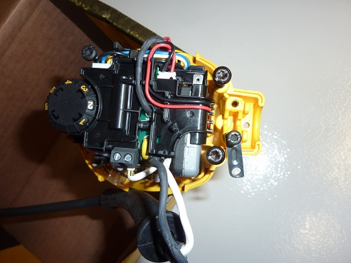
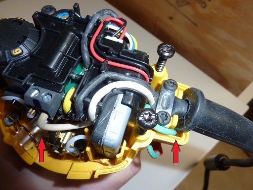
Remove the Cover of the router
Unscrew the bracket holding the power cord down with a hex keys
Pull the power cord clear of the area needing to be drilled
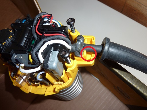
Using a 1/8” drill bit a hole in the location, drill a hole in the location shown
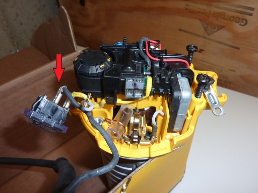
Remove the power cord from the power switch and router
Take the strain relief and snap-on-ferrite off of the old cable and transfer it to the new one
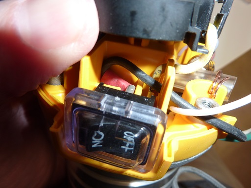
If you have 90 degree spade connectors attach one to the black/hot of the new power cord and connect to the existing power switch
If not you don’t then just cut the black/hot wire and solder/butt splice it to the HOT on the new power and connect it to the power switch. Use heat shrink on the splice also.
Re-connect the power switch
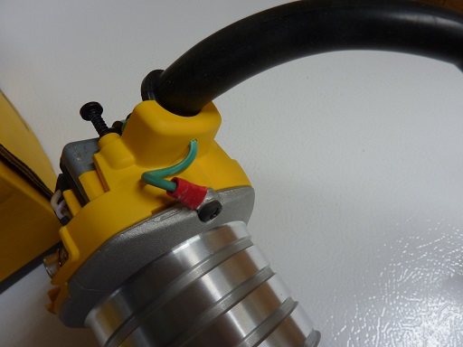
Route the green earth ground wire from the power cord down into the hole you made
- Crimp/solder a ring termal connector to the earth ground. .. note: Technically you can skip the connector if you don’t have one
- Unscrew the existing screw in the router housing and attach the ring terminal or raw ground wire to it.
- Replace the screw into the router housing
- If you have a multimeter (and you really should), test continuty between the router housing and the ground pin on the power cord to confirm it is now grounded
| [Ref] | This section is summarized from a carbide3d forum post |