Section 5: Install Y Motor Mounts and Build the Gantry
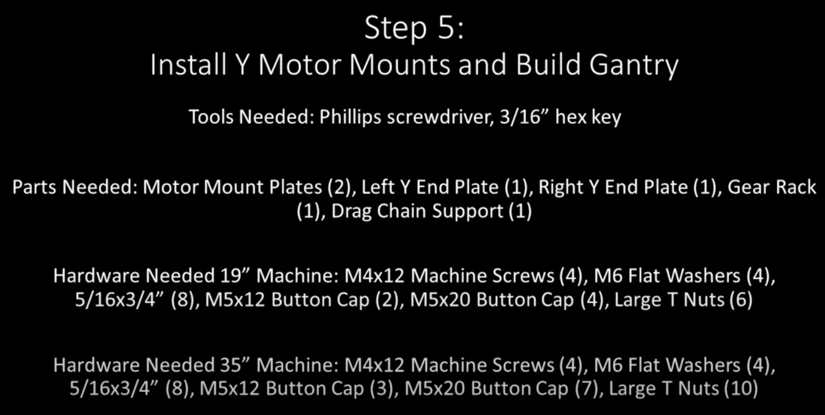
Section 5a: Supplies needed
- Parts Needed (Common)
- Motor Mounts (2)
- Left Y End Plate (1)
- Right Y End Plate (1)
- Gear Rack (1)
- Drag Chain Support (1)
- M6 Flat Washers (4)
- Parts Needed (19”)
- 5/16x3/4” (8)
- M5x12mm Button Cap Screws (2)
- M5x20mm Button Cap Screws (4)
- Large T Nuts (6)
- Parts Needed (35”)
- M4x12 Machine Screws (4)
- 5/16x3/4” Button Cap Screws (8)
- M5x12mm Button Cap Screws (3)
- M5x20mm Button Cap Screws (7)
- Large T Nuts (10)
- Tools Needed:
- #2 Phillips head screwdriver
- 3/16” hex key
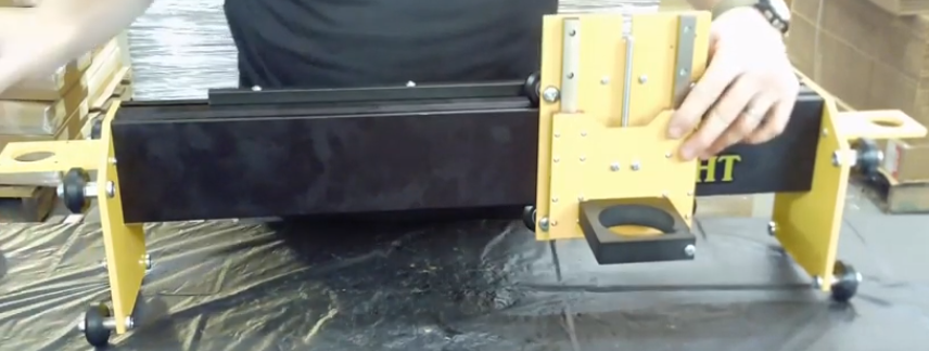
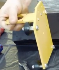
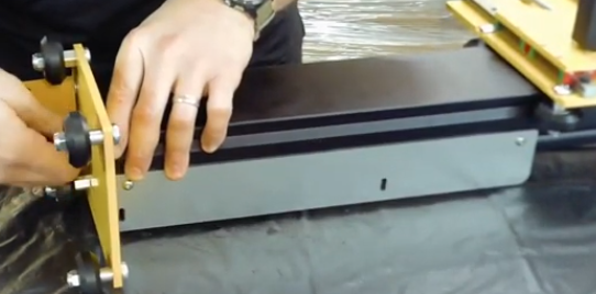
Section 5b: Attaching the Y motor mount to the Left and right Gantry plates
YouTube Bookmark: https://youtu.be/ZkZot-WJXo8?t=1951
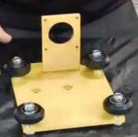
The motor mount will attach to the back of the Y-Plates on the same side as the V-Wheels
Insert two M4x12mm screws through each of the Y-Plates
Place an M6 Washer over each screw
Warning
- DO NOT forget the washers. They are key to properly aligning the pinions and you’ll be really annoyed fixing it later
- Be careful not to cross thread the screw
Note
One of the mounting plate m4x12mm screws will be blocked by the Gantry once its installed so be sure to secure in tightly now
Optionally apply loktite to the screws now
Ensure that the motorplate isn’t canted in either direction as you fasten it.
After you get the screws loosely fastened, push down on the plate to ensure the screws are at the bottom of their free fitment
Verify it is square with your machinist square
Measure the distance from the bottom of the motor plate to the bottom of the Y Gantry plate on both sides. If its crooked then measurements won’t match
Repeat for the other Y Plate
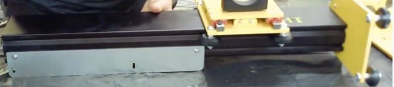
Section 5c: Attaching the gear rack to the gantry
YouTube Bookmark: https://youtu.be/ZkZot-WJXo8?t=2057
Note
The front of the gantry is closet to the V groove and the rear is closer to the T Slot If your gantry shipped with the sticker on held on with masking tape now is a good time to apply it to the front face-off the gantry. The author refuses to answer any questions on why they felt this note was needed and/or where the sticker not their unit may be located
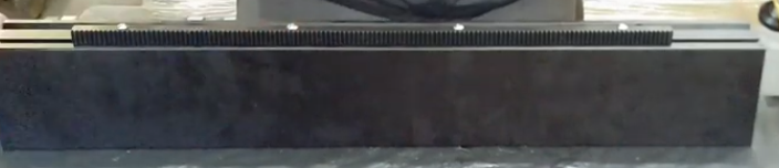
Gather 1 of the 3 gear racks (toothed strips of metal)
For the 19” you will be using 4 T-Nuts and 4 M5x20mm
For the 35” you will be using 7 T-Nuts and 7 M5x20mm
Slip the screws thru the holes in the get rack.
Loosely attach a T-Nut to each screw so it is just barely held on
Get the T Nuts all aligned in the same direction
Ensure that the teeth on the gear rack are facing the back side of the gantry and slide the T-Nuts into the T-Track on the Gantry and roughly center the gear rack.
Loosely tighten all of the screws.
Use a set of calipers or even a tape measure to ensure the gear rack is properly centered onto the gantry approximately 88.5mm from each end.
- ..note:: The gear being crooked on the gantry will cause binding in the final assembly when jogging the router. Getting the positioning even is key to a successful end result with all 3 gear racks. Carefully measure the back of the gear rack to the front of the gantry at each screw and adjust as necessary for even spacing mine was 7mm at each screw
Cinch down the screws but don’t loktite them yet
Section 5d: Attaching the X Plate to the gantry
YouTube Bookmark: https://youtu.be/ZkZot-WJXo8?t=2250
Warning
Be careful moving the X-Plate around. You don’t want to tilt it and have the bearings fall off the rails
Warning
Carefully inspect both ends of the gantry extrusion. Any burr will prevent the Y-Plates from sitting flush to the extrusion. Take a thin file and shave down any burrs to ensure the plates will sit flush.
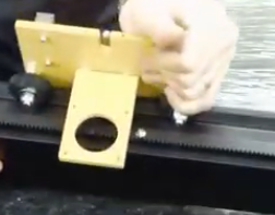
With the front of the gantry rail (sticker side) facing the front of the X-Plate (router mount side) slide the V-Slot onto the V-Wheels of the X-Plate
Note
- If your M8 Screws are too tight on the V Wheels you may not be able to slide onto the gantry V-Slot. If this happens just loosen your M8 screws.
- If you have burrs at the openings of the track, which happened to some due to shipping damage, taking a file to smooth out the track opening is a good idea to protect the V-Wheels.
If your M8 screws were loose tighten them now
Fine grained tightening is done by taking an 8mm wrench and turning the eccentric spacers to add a bit more pressure on the wheels and rails
When done you should be able to smoothly slide the X-Plate up and down the Gantry. If there is any binding check that each V-Wheel is of equal tightness
Section 5e: Attaching the Right Y-Plate to the gantry
YouTube Bookmark: https://youtu.be/ZkZot-WJXo8?t=2333
Note
The Y-Gantry plates have sides to them. The longer slope on the plate top should point towards the front of the gantry when the V-Wheels face away from the gantry
| Left Gantry Plate | Right Gantry Plate |
|---|---|
 |
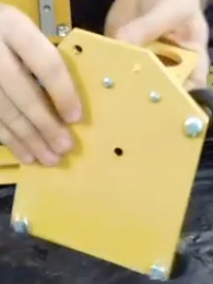 |
Line up the Right Gantry Plate with the right side of the Gantry’s 4 pre-tapped holes
Optionally apply loktite to the 4 screws
Take 5/16”x3/4” Button cap screws and fasten the Right Gantry plate to the gantry finger tight .. warning:: You will likely be rotating the gantry to align things. Be very careful the bearings don’t fall off the Z-Plate while doing this
Using a 5/16” socket gradually tighten each of the screws a little at a time to get them consistent and the plate is squared and flush.
Note
The screws should go in smoothly, if they resist then something is wrong, back out and reseat the screw
Verify the plate is on square to the gantry
Section 5f: Attaching the drag chain support
Turn the gantry so the back is facing you.
Warning
When doing this don’t let your Z-Plate fall off
Pass an M5x12mm button cap screw through each hole (not slot) in the drag chain support and attach a T-Nut to each
Position the drag chain support on the back left side (opposite of the right gantry plate and slide the T-nuts into the T-Track.
Slide the drag chain support just onto the T-Track staying very close to the end of the gantry
Secure the screws tightly to the T Nuts
Section 5g: Attaching the Left Y-Plate to the gantry
Now its time to attach the Left Gantry plate
Just like the Right plate align the plate to the the predrilled holes in the gantry with the V-Wheels facing out
Optionally apply loktite to the 4 screws
Optionally supporting the end of the gantry with a block of wood makes it much easier to attach the Left plate and avoid any canting while cinching it down
Take 5/16”x3/4” Button cap screws and fasten the Right Gantry plate to the gantry finger tight
..warning:: You will likely be rotating the gantry to align things. Be very careful the bearings don’t fall off the Z-Plate while doing this
Using a 5/16” socket gradually tighten each of the screws a little at a time to get them consistent and not can’t the plate.
Note
The screws should go in smoothly, if they resist then something is wrong, back out and reseat the screw
Verify the plate is on square to the gantry
Warning
- At this point the gantry is now a wheeled vehicle, don’t let it drive off your work bench
- Thegantry is now fairly heavy with the 3 plates attached. Practice proper back/spine safety when moving it. Remember kids a spine is a terrible thing to waste.
Section 5g: Testing the X-Plate movement
Just like in Section 4 where you ensured that the Z-Axis travesed up and down smoothly, now you want to ensure the X Plate traverses the Gantry smoothly.
Carefully position the Gantry so it is sitting on the 4 V Wheels and facing forward.
Slide the X-Plate down the extrusion by gently pushing it with a single finger.
Watch the 4 V-Wheels, they should all be spinning equally
Do you feel a stuttering? This is a sign that 1 or more of the V Wheels is too tight.
- If you place your finger by 1 V-Wheel and push you may feel more resistance closer or further from you.
- Push up on the bottom of the X-Plate and then slide the plate to the left and right. If that slight lift reduces stuttering then you need to tighten the lower V-Wheels slightly. If there is no change you need to tune the upper wheels.
- Assuming you marked your Eccentrics with a sharpie they should be in their loosest postion. If they aren’t use a wrench to rotate them to their loose spot. You may need to hold the M8 Screw with a #2 screwdriver.
- If it feels like the stuttering is on the top V-Wheels then use a wrench and screwdriver to loosen the Nylock nut 1/8 to 1/4 turn.
- Test how the X-Plate slides now. If there is no stuttering you win! If there is, loosen the other Nylock nut.
- If the stuttering is gone then use your wretch to turn the eccentry on 1 wheel 1/8 or less of a turn.
- Keep tightening until the stuttering returns then backoff till its gone. If rotating the eccentric never causes the stutter then you loosened the nylock nut too much so go back and restart the process.
- If after all this you still have tracking problems there is a real risk your X-Plate is warped. You’ll want to go all the way back to Section 4 and recheck your X-Plate on both sides.
- If none of this works, post to the Facebook group and we will help you.